Tuesday, November 11, 2025

Classification of columns


Classification of columns
 

A column is defined as a compression member, the effective

 length of which exceeds three times the least lateral dimension. 

Compression members, whose lengths do not exceed three times

 the least lateral dimension, may be made of plain concrete.

 A column forms a very important component of a structure.

 Columns support beams which in turn support walls and slabs. 

It should be realized that the failure of a column results in the 

collapse of the structure. The design of a column should therefore 

receive importance.


Introduction:


A column is a vertical structural member supporting axial 

compressive loads, with or without moments. The cross-sectional 

dimensions of a column are generally considerably less than its height.

 Columns support vertical loads from the floors and roof and transmit 

these loads to the foundations. The more general terms compression 

members and members subjected to combined axial load and

 bending are sometimes used to refer to columns, walls, and members 

in concrete trusses or frames. These may be vertical, inclined, or horizontal. 

A column is a special case of a compression member that is vertical.

 Stability effects must be considered in the design of compression members.


Classification of columns


A column may be classified based on different criteria such as:
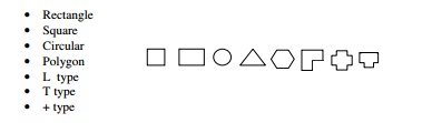
 

1.Based on shape

       I.            Rectangle 

                          Square

 III.            Circular

IV.            Polygon

   V.            L  type

VI.            T type

VII.            + type


2.Based on slenderness ratio or height

Short column and Long column or Short and Slender Compression Members


A compression member may be considered as short when both the slenderness 

ratios namely lex/D and ley/b are less than 12: Where

lex= effective length in respect of the major axis,

 D= depth in respect of the major axis, 

ley= effective length in respect of the minor axis, and

 b = width of the member.


It shall otherwise be considered as a slender or long compression member.

The great majority of concrete columns are sufficiently stocky (short) that

 slenderness can be ignored. Such columns are referred to as short columns.

 Short column generally fails by crushing of concrete due to axial force. 

If the moments induced by slenderness effects weaken a column appreciably,

 it is referred to as a slender column or a long column. Long columns

 generally fail by bending effect than due to axial effect. Long column 

carry less load compared to long column. 

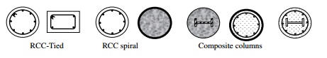
3.Based on pattern of lateral reinforcement


      Tied columns with ties as laterals


      columns with Spiral steel as laterals or spiral columns


Majority of columns in any buildings are tied columns. 

In a tied column the longitudinal bars are tied together with smaller

 bars at intervals up the column. Tied columns may be square, rectangular, 

L-shaped, circular, or any other required shape. Occasionally, when high

 strength and/or high ductility are required, the bars are placed in a circle, 

and the ties are replaced by a bar bent into a helix or spiral. Such a 

column, called a spiral column. Spiral columns are generally circular, 

although square or polygonal shapes are sometimes used. The spiral acts to 

restrain the lateral expansion of the column core under high axial loads and,

 in doing so, delays the failure of the core, making the column more ductile. 

Spiral columns are used more extensively in seismic regions. If properly 

designed, spiral column carry 5% extra load at failure compared to similar

 tied column.

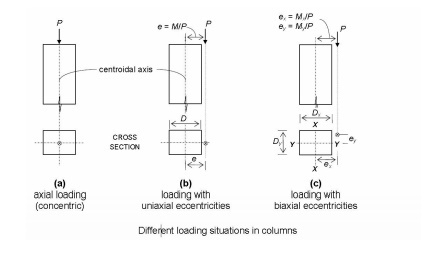
4.Based on type of loading


      Axially loaded column or centrally or concentrically loaded column (Pu)

      A column subjected to axial load and unaxial bending (Pu + Mux) or (P + Muy)

A column subjected to axial load and biaxial bending (Pu + Mux + Muy)


5. Based on materials

Timber, stone, masonry, RCC, PSC, Steel, aluminium , composite column


Sunday, November 2, 2025

๐Ÿ  Low-Cost Housing: A Sustainable Approach to Affordable Living


๐Ÿ  Low-Cost Housing: A Sustainable Approach to Affordable Living

Introduction
Low-cost housing is a progressive concept aimed at making home construction economical and sustainable without compromising on quality, durability, or safety. It focuses on effective budgeting, optimized use of locally available materials, and the adoption of innovative construction technologies.

A common misconception is that low-cost housing involves cheap or substandard ma

terials. In reality, it emphasizes resource management, efficiency, and intelligent design. The goal is to create durable, comfortable, and safe housing that remains affordable for all sections of society.


๐Ÿ’ฐ Understanding Building Costs

The total construction cost of a building can generally be divided into two major components:

  • Building material cost: 65%–70%

  • Labour cost: 30%–35%

By using locally available materials, adopting efficient construction techniques, and ensuring better planning, both these costs can be significantly reduced. Cost efficiency is achieved not by cutting quality, but by selecting better materials, optimizing design, and managing time effectively.


๐Ÿงฑ Areas Where Cost Can Be Reduced

  1. Reduce Plinth Area – Use thinner wall concepts like 15 cm solid concrete block walls.

  2. Use Local Materials – Adopt soil-cement blocks instead of conventional burnt bricks.

  3. Energy Efficiency – Use materials that require less energy for production, such as concrete blocks.

  4. Eco-Friendly Alternatives – Replace wooden doors and windows with RCC or steel frames.

  5. Efficient Planning – Preplan and rationalize design to minimize waste and avoid rework.

  6. Avoid Unnecessary Components – Include only essential structural and aesthetic elements.


⚙️ Cost Reduction through Practical Methods

1. Foundation

Foundation typically consumes 10–15% of total building cost.

  • Use 2 ft. depth for normal soil instead of 4 ft.

  • Adopt arch foundations in ordinary soil for 40% cost savings.

  • For black cotton soil, use under-reamed pile foundation for 25% cost reduction.

2. Plinth

  • Keep plinth height at 1 ft. above ground level using 1:6 cement mortar.

  • Replace plinth slabs with brick-on-edge flooring to save 35–50% of cost.

  • Provide impervious layers around the building to prevent erosion.

3. Walling

Use 6″ to 9″ thick external walls and 4½″ internal walls. Recommended techniques include:

๐Ÿ”น Rat-Trap Bond Wall

A cavity wall technique that enhances thermal comfort and saves 25% of bricks and 15% of masonry cost. It also provides a decorative finish, eliminating the need for plastering.


Rat trap bond stands for a most recognized brick masonry method of wall construction. Under this system, the bricks are arranged in a vertical position rather than the traditional horizontal position. In this way, a cavity (hollow space) is formed inside the wall.

Detail Construction Process

The rat trap bond construction mainly refers to a modular type of masonry construction in which the masonry bricks are provided on edges so that the shiner and rowlock become detectable. As a result, 110 mm face is uncovered from front elevation (for the brick size of 230mmx110mmx75mm). It provides an internal cavity to the wall that leads to efficient thermal insulation.

Benefits of Rat Trap Bond

The cavities function as good thermal insulators in the masonry wall. As a result, the temperature inside turns out to be cooler in summer and hotter in winter.

Rat Trap masonry uses fewer bricks and mortar reducing the cost of masonry is curtailed up to 30% in relation to traditional brick masonry because less bricks and mortar are required for rat trap masonry.

The number of bricks utilized in building the rat trap masonry is 470 but in traditional masonry, it should be 550.

Walls built-up with rat trap masonry can be applied as load-bearing and a thick partition wall.

When Rat-trap bond is uncovered, an aesthetically pleasing wall surface is formed and the plastering cost and painting are excluded.

Since this type of masonry contains 30% of cavities, the dead load of the structure is minimized and consequently the numbers of the structure supporting members like column and footing are curtailed.

For the structural safety of mortar, reinforcement bars are provided through the cavity until the foundation.

This type of walling technology is long-lasting and the maintenance costs are less for the buildings which are built up long ago.

Drawbacks of Rat Trap Bond

As the cavities are created in the masonry, the building does not have good quality sound insulations.

Without the help of skilled labor, this type of masonry construction is not possible.

If the exterior surface is not plastered, it should be cleaned on a regular basis.

Special care and attention should be taken at the time of designing and constructing rat trap bond masonry.

Bamboo Construction
Description:

Bamboo is a sustainable, locally available, and low-cost construction material.

It has high tensile strength, comparable to mild steel, and is suitable for rural and eco-friendly housing.

Construction Details:

Used as reinforcement in slabs, beams, and columns (after proper treatment).

Bamboo poles are tied together using coir ropes, steel wires, or bolts.

Joints are carefully designed to resist tension and compression.

Bamboo mats can also be used for wall panels, roof trusses, and flooring.

Advantages:

✅ Renewable and easily available material.
✅ Light in weight and easy to handle.
✅ Environmentally friendly – carbon-neutral construction.
✅ Cost-effective for rural housing.


Compressed Stabilized Earth Blocks (CSEBs) are a highly effective low-cost construction technique primarily because they use locally available soil, which drastically cuts down on material and transportation costs. CSEB construction can be up to 40% cheaper than conventional fired brick masonry. 
Key Cost-Saving Techniques & Advantages
Local Material Sourcing: The main cost saving comes from using the soil excavated directly from or near the construction site, eliminating expensive transportation.
Reduced Embodied Energy: CSEBs are air-cured and sun-dried, requiring no energy-intensive firing process like traditional bricks. This makes the production process more energy-efficient and cheaper.
Lower Mortar and Plaster Needs: CSEBs have uniform shapes and sizes, and interlocking blocks are available, which minimize the need for mortar during wall construction. Walls can often be left exposed (unplastered) due to their aesthetic appeal and smooth finish, further reducing expenses.
Utilizing Local Labor: The production process is relatively simple and labor-intensive, allowing for the use of locally available, semi-skilled labor, which can be trained in a short time. This provides local employment and reduces reliance on expensive, specialized masons for the block production phase.
Thermal Efficiency: CSEB walls provide excellent thermal insulation, which helps maintain comfortable indoor temperatures (cooler in summer, warmer in winter). This reduces long-term operational costs by lowering energy consumption for heating and cooling systems.
Self-Help Construction: In community projects, local residents can be involved in the self-production of blocks and construction of houses, leading to significant cost savings (potentially up to 50% on the house's total cost). 
Cost Comparison (Indicative)
Material Cost per m³ of Masonry (Indicative) Cost Saving vs. Fired Bricks
Fired Bricks (Base Cost) -
CSEB 15-20% less expensive Up to 40% overall project saving
Stabilized Rammed Earth Walls 20-30% less than CSEB walls 30-50% less expensive than fired bricks
Important Considerations
Soil Suitability: Not all soil types are suitable; testing the local soil is essential to determine its properties and the optimal percentage of stabilizer (usually 5-8% cement or lime) required for durability and strength.
Quality Control: Strict quality control during production and construction is vital to ensure the final structure is robust and durable, particularly in resisting water and seismic events.
Design for Durability: Proper design, such as providing adequate roof overhangs and foundations, is important to protect the walls from excessive moisture and erosion.

๐Ÿ”น Concrete Block Walling

Reduces energy consumption, saves 10–25% in total cost, and allows faster construction with minimal plastering.

๐Ÿ”น Soil Cement Block Technology

Involves mixing soil with 5–10% cement, pressing it into blocks, and curing. Offers 15–20% savings and eliminates plastering.


๐Ÿšช Doors and Windows

Avoid expensive wood.

  • Use concrete or steel frames – saves 30–40%

  • Use block boards or fiber boards for shutters – saves 25%

  • Incorporate brick jali work or precast ventilators for natural light and ventilation.


๐Ÿงฑ Lintels and Chajjas

  • Replace RCC lintels with brick arches for small spans – saves 30–40%.

  • Adds both structural efficiency and architectural beauty to buildings.


๐Ÿ—️ Roofing Techniques

๐Ÿ”น Filler Slabs

Use filler materials like bricks, tiles, or hollow blocks in the tension zone of slabs.

  • Saves 20–25% in concrete and steel.

  • Enhances aesthetics and provides insulation.

๐Ÿ”น Jack Arch Roofs

Constructed using small arches between steel joists.

  • Saves cement and steel.

  • Best suited for hot climates.

๐Ÿ”น Ferrocement Channels or Shell Units

Precast ferrocement panels provide the same strength as RCC slabs with 30–40% cost savings.

  • Light in weight

  • Faster construction

  • Ensures better quality control


๐Ÿก Finishing Works

Cost of finishing (plumbing, electrical, and painting) depends on product choice.
Using locally sourced fittings and phased implementation can further reduce costs while maintaining quality.


๐ŸŒฑ Conclusion

Low-cost housing is not about building cheaper—it’s about building smarter, sustainable, and resource-efficient homes.
By adopting techniques like rat-trap bonding, soil-cement blocks, filler slabs, and RCC frames, significant cost savings (20–40%) can be achieved without compromising on quality or aesthetics.

Ultimately, low-cost construction is a step toward affordable, sustainable, and environmentally responsible development, making the dream of a home accessible to everyone.


Tuesday, September 30, 2025

Different Types of Loads in Buildings

 Different Types of Loads in Buildings  

 General 

 In structural design, account shall be taken of the dead, imposed and wind loads and forces such as those caused by earthquake, and effects due to shrinkage, creep, temperature, etc, where applicable.

The loads on buildings and structures can be classified as vertical loads, horizontal loads and longitudinal loads. 

The vertical loads consist of dead load, live load and impact load. 

The horizontal loads consist of wind load and earthquake load. 

The longitudinal loads i.e. tractive and braking forces are considered in special cases of design. The estimation of various loads acting is to be calculated precisely. Indian standard code IS: 875–1987 

 1 Dead Loads-  Dead loads shall be calculated on the basis of unit weights which shall be established taking into consideration the materials specified for construction.

Alternatively, the dead loads may be calculated on the basis of unit weights of materials given in IS 875 (Part I). Unless more accurate calculations are warranted, the unit weights of plain concrete and reinforced concrete made with sand and gravel or crushed natural stone aggregate may be taken as 24 kN/m” and 25 kN/m” respectively. 

2 Imposed Loads-Definition- As per IS 875(II) The load assumed to be produced by the intended use or occupancy of a building, including the weight of movable partitions, distributed, concentrated loads, load due to impact and vibration, and dust load but excluding wind, seismic, snow and other loads due to temperature changes,
Imposed loads  shall be assumed in accordance with IS 875 (Part II) Anything in a building that is not fixed to the structure can result in a live load since it can be moved around.
e.g for Residential bungalow live load considered as 2kN/m. 
As per IS 875( Part II) The use of the term ‘live load’ has been modified to ‘imposed load’ to cover not only the physical contribution due to persons but also due to nature of occupancy, the furniture and other equipment's which are a part of the character of the occupancy. 
 The imposed loads on floors and roofs have been rationalized based on the codified data available in large number of latest foreign national standards, and other literature. Further, these values have been spelt out for the major occupancies as classified in the National Building Code of India as well as the various service areas appended to the major occupancies.

3 Wind Loads shall be assumed in accordance with IS 875 (Part III).Wind loads can be applied by the movement of air relative to a structure, and analysis draws upon an understanding of meteorology and aerodynamics as well as structures. Wind load may not be a significant concern for small, massive, low-level buildings, but it gains importance with height, the use of lighter materials and the use of shapes that may affect the flow of air, typically roof forms.

In IS 875(III) briefly given wind forces and their effects ( static and dynamic ) that should be taken into account when designing buildings, structures and their components .

4 Snow Loads shall be assumed in accordance with  IS 875 (Part IV). 

5 Earthquake Forces The earthquake forces shall be calculated in accordance with IS 1893. Earthquake load takes place due to the inertia force produced in the building because of seismic excitations. Inertia force varies with the mass. The higher mass of the structure will imply that the earthquake loading will also be high.

6 Shrinkage, Creep and Temperature Effects-  If the effects of shrinkage, creep and temperature are liable to affect materially the safety and serviceability of the structure, these shall be taken into account in the calculations in accordance with IS 875 (Part V). 

In ordinary buildings, such as low rise dwellings whose lateral dimension do not exceed 45 m, the effects due to temperature fluctuations and shrinkage and creep can be ignored in &sign calculations.

 7 Other Forces and Effects-  In addition, account shall ‘be taken of the following forces and effects if they are liable to affect materially the safety and serviceability of the structure: 

a)  Foundation movement (see IS 1904), 

b) Elastic axial shortening, Soil and fluid pressures [see IS 875 (Part S)], 

c) Vibration, Fatigue, Impact [see IS 875 (Part 5)], 

d) Erection loads [see IS 875 (Part 2)], and Stress concentration effect due to point load and the like.


Load Combinations - IS 875(V)-1987

 In the absence of such load combination guidelines, the following loading combinations, whichever combination produces the most unfavorable effect in the building, foundation or structural member concerned may be adopted as a general guidance. It should also be recognized in load combinations that the simultaneous occurrence of maximum values of wind, earthquake, imposed and snow loads is not likely, 

 a) DL 

 b) DL+IL 

 c) DL+WL 

 d) DL+EL 

 e) DL+TL 

 f) DL+IL+ W

g) DL+IL+EL

h) DL+ IL+ TL

i) DL+WL+TL 

j) DL+WL+TL

k) DL+EL+TL

m) DL+IL+WL+TL 

 n) DL+IL+EL+TL 

Where DL = dead load, IL = imposed load, WL = wind load, EL = earthquake load, IL = temperature load.

References

 IS 456 (2000): Plain and Reinforced Concrete - Code of Practice [CED 2: Cement and Concrete] July 2000 IS. 456 : 2000 (R••fflrmed2005) Indian Standard PLAIN AND REINFORCED CONCRETE ­ CODE OF PRACTICE (Fourth Revision) 
Explanatory Handbook on Earthquake Resistant Design and Construction (IS : 1893 .
 Loading Code-CODE OF PRACTICE FOR DESIGN LOADS IS 875 Part (1to5)

Friday, August 22, 2025

Limit State Design in Torsion: Equilibrium Torsion and Compatibility Torsion

Limit State Design in Torsion: Equilibrium Torsion and Compatibility Torsion

Introduction

In reinforced concrete structures, torsion often occurs in combination with flexure shear. While pure torsion, as seen in metal shafts, is rare in reinforced concrete, the interaction of torsion with bending moments and flexural shear in concrete beams is complex. To simplify design, codes provide streamlined procedures, blending theory and experimentation. This chapter explores the general behavior of reinforced concrete beams under torsion and elucidates the concepts of equilibrium torsion and compatibility torsion.

Equilibrium Torsion and Compatibility Torsion

Torsion can manifest in various ways during load transfer in structural systems. In reinforced concrete design, two terms, namely "equilibrium torsion" and "compatibility torsion," describe different torsion-inducing situations. Equilibrium torsion arises from eccentric loading, relying solely on equilibrium conditions to determine twisting moments. Compatibility torsion, on the other hand, is induced by an angle of twist, and the resulting twisting moment depends on the torsional stiffness of the member.

In certain situations, both equilibrium and compatibility torsion may coexist, such as in circular beams supported on multiple columns.

Equilibrium Torsion

Equilibrium torsion involves twisting moments developed in a structural member to maintain static equilibrium with external loads. This torsion is independent of the torsional stiffness of the member. The magnitude of the twisting moment is determined by statics alone, and the member must be designed to resist this full torsion. Common scenarios for equilibrium torsion include beams supporting lateral overhanging projections or beams with curved plans subjected to gravity loads.

Ends of the member must be suitably restrained to effectively resist induced torsion.

Compatibility Torsion

Compatibility torsion is induced by rotations applied at one or more points along the length of the member. The twisting moments induced are directly dependent on the torsional stiffness of the member. Analysis involves compatibility conditions due to rotational deformations. Torsional stiffness is significantly reduced by torsional cracking, allowing designers to simplify structural analysis by neglecting torsional stiffness. However, to control cracking and enhance ductility, minimum torsional reinforcement is recommended.

Estimation of Torsional Stiffness

Torsional stiffness in reinforced concrete members is influenced by the amount of torsional reinforcement. In the linear elastic phase, torsional stiffness is similar to that of the plain concrete section. However, once torsional cracking occurs, there is a drastic reduction in stiffness, emphasizing the importance of proper torsional reinforcement.

In conclusion, understanding equilibrium and compatibility torsion is crucial for designing safe and resilient reinforced concrete structures. Equilibrium torsion relies on static equilibrium conditions, while compatibility torsion considers deformations induced by twists, requiring an accurate estimation of torsional stiffness. Striking a balance between these torsional considerations ensures the integrity and durability of reinforced concrete members under various loading conditions.


Wednesday, November 27, 2024

Spire test in Theodolite

Spire test in Theodolite 

Condition- To make the horizontal axis perpendicular to vertical axis.

Necessity- By mean of the 2nd and 3rd adjustment, we ensure that line of sight will revolve in vertical plane. The adjustment become essential in all work necessitating motion of the telescope in altitude.

Spire test-

enter image description here

  1. Set up the instrument over high building or other object on which there is defined point at a considerable altitude such as flag pole , lighting etc.
  2. And mark a well defines point A at a considerable height.
  3. Level the instrument accurately thus making vertical axis truly vertical.
  4. Sight the point as shown in fig and horizontal motion clamped depress the telescope and set a point P on or near the ground.
  5. Unclamped and transit the telescope and swing through 1800 with telescope inverted again sight on P.
  6. Depress the telescope as before, if the light of sight fall on P, the horizontal axis is perpendicular to vertical axis.

Adjustment

  1. It not marks another point Q in the line of sight on the wall at the same level as P.
  2. Mark point R midway between P and Q sight on point R.
  3. Clamp the upper motion.
  4. Raise the telescope.
  5. The line of sight will now strike the point A.

Classification of columns

  Classification of columns   A column is defined as a compression member, the effective  length of which exceeds three times the least late...